Wide band O2 sensor
http://www.aa1car.com/library/wraf.htm
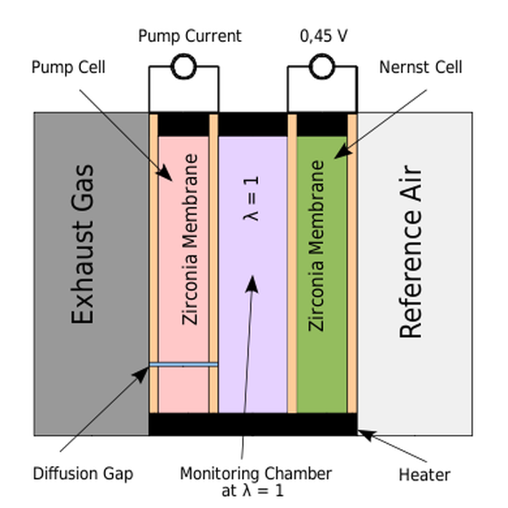
Internally, wideband O2 sensors and A/F sensors appear to be similar to conventional zirconia planar oxygen sensors. There is a flat ceramic strip inside the protective metal nose cone on the end of the sensor. The ceramic strip is actually a dual sensing element that combines a "Nerst effect" oxygen pump and "diffusion gap" with the oxygen sensing element. All three are laminated on the same strip of ceramic.
Exhaust gas enters the sensor through vents or holes in the metal shroud over the tip of the sensor and reacts with the dual sensor element. Oxygen diffuses through the ceramic substrate on the sensor element. The reaction causes the Nerst cell to generate a voltage just like an ordinary oxygen sensor. The oxygen pump compares the change in voltage to the control voltage from the PCM, and balances one against the other to maintain an internal oxygen balance. This alters the current flow through the sensor creating a positive or negative current signal that indicates the exact air/fuel ratio of the engine.
The current flow is not much, usually only about 0.020 amps or less. The PCM then converts the sensor's analog current output into a voltage signal that can then be read on your scan tool.
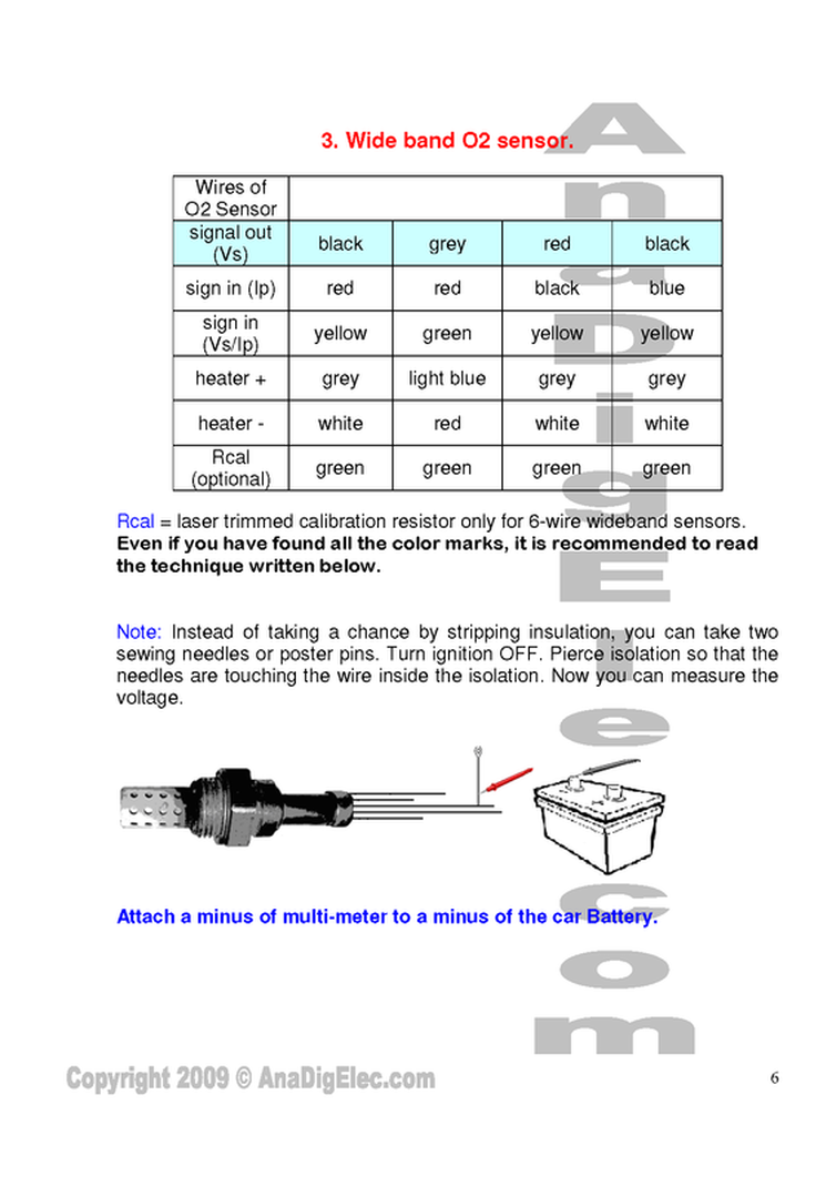
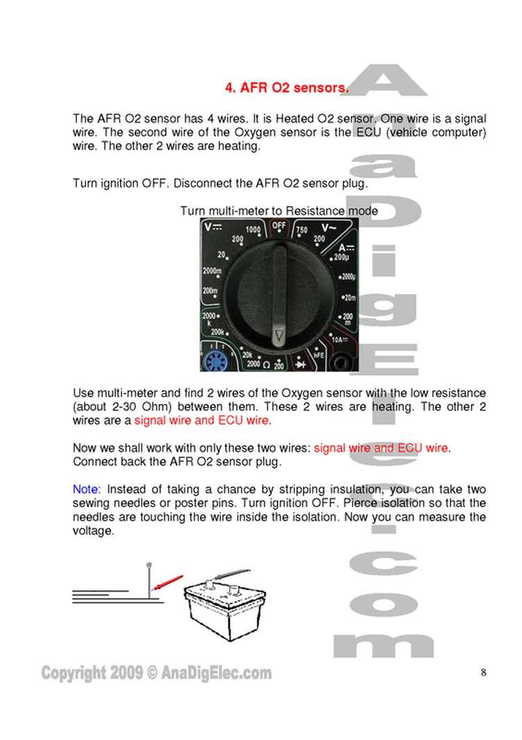
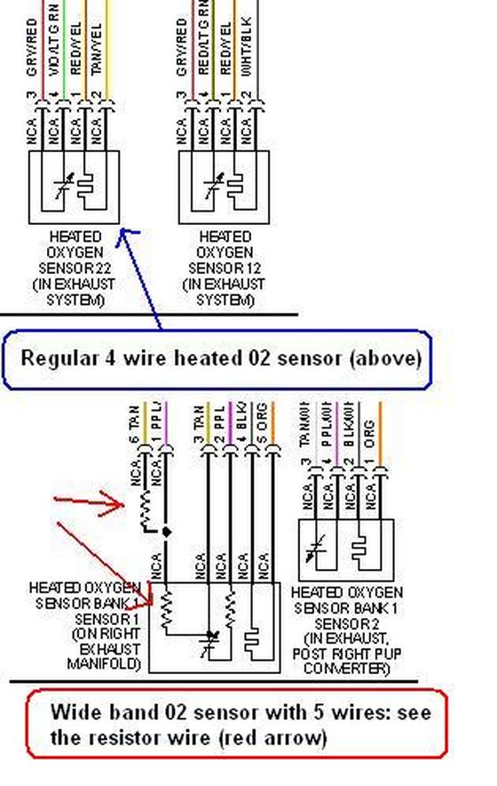
What's the difference between a wideband O2 sensor and an A/F sensor? Wideband 2 sensors typically have 5 wires while most A/F sensors have 4 wires.
http://en.wikipedia.org/wiki/Oxygen_sensor
It is based on a planar zirconia element, but also incorporates an electrochemical gas pump. An electronic circuit containing a feedback loop controls the gas pump current to keep the output of the electrochemical cell constant, so that the pump current directly indicates the oxygen content of the exhaust gas.
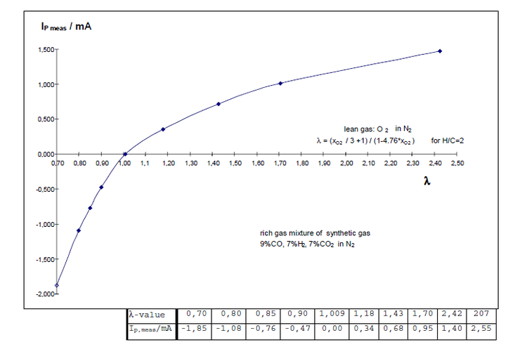
λ-value and output current (Bosch)
output is voltage
|
output is current
|
The heater (for Bosch)
The heater poweris closed-loop controlled while the measurement is done, so that a nominalsensor internal resistance of RIN=80Ω (measured with 1...4 kHz) is reached,this corresponds to a sensor ceramic temperature of approx. 750°C in new state.
TECH TIPS
* On Honda 5-wire "Lean Air Fuel" (LAF) sensors, the 8-pin connector pin for the sensor contains a special "calibration" resistor. The value of the resistor can be determined by measuring between terminals 3 and 4 with an ohmmeter, and will be 2.4K ohms, 10K ohms or 15k ohms depending on the application. If the connector is damaged and must be replaced, the replacement must have the same value as the original. The reference voltage from the PCM to the sensor on these engines is 2.7 volts.
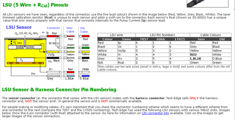
* Saturn also uses a special trim resistor in their wideband O2 sensor connector (pins 1 & 6). The resistor is typically 30 to 300 ohms. The PCM supplied reference voltage is 2.4 to 2.6 volts.
* If a O2 sensor, wideband O2 sensor or A/F sensor has failed because of coolant contamination, do not replace the sensor until the leaky head gasket or cylinder head has been replaced. The new sensor will soon fail unless the coolant leak is fixed.
* Some early Toyota applications with A/F sensors provide a "simulated" O2 sensor voltage to be displayed on a scan tool. The actual value was divided by 5 to comply with early OBD II regulations. Those regulations have since been revised, but be aware if you get a "funky" display on your scan tool
How to install a O2 sensor
http://www.wbo2.com/lsu/position.htm
Basic test of a O2 sensor
How does the wires mean and connection
http://www.wbo2.com/cable/lsuconns.htm
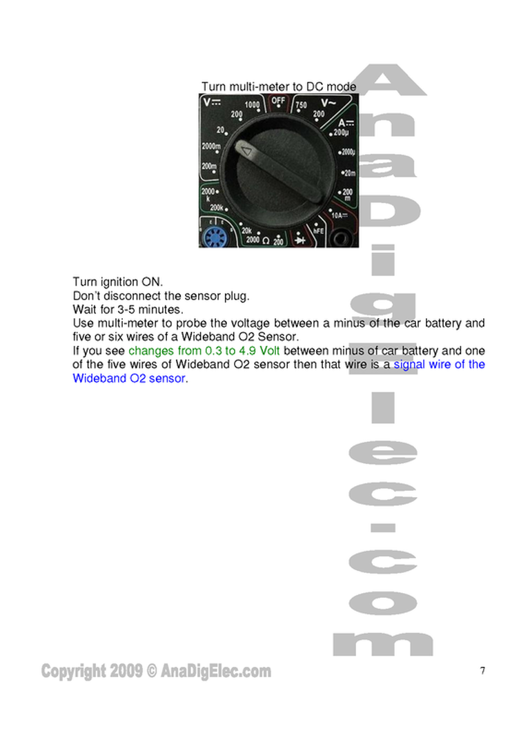
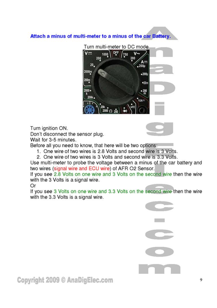
How to test a wide band O2 sensor