ignition waveforms
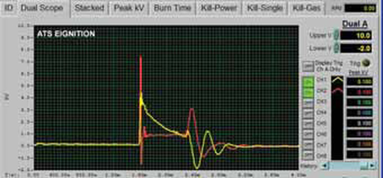
In Fig. 9 below, the yellow trace has a 20k resistor placed in the ignition wire. The red trace is the companion cylinder and the point of plasma is normal. The point of plasma on the yellow trace is 2.3kV higher than normal, indicating resistance in the circuit.
http://www.motor.com/magazine/pdfs/052005_04.pdf
http://www.motor.com/magazine/pdfs/052005_04.pdf
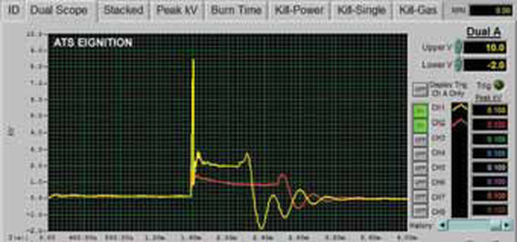
the yellow trace has a .20-in. gap between the ignition wire and the spark plug. The red trace is the companion cylinder and the point of plasma is normal. On the yellow trace, the point of plasma is 1.2kV higher than normal, indicating resistance in the circuit.
http://www.motor.com/magazine/pdfs/052005_04.pdf
http://www.motor.com/magazine/pdfs/052005_04.pdf
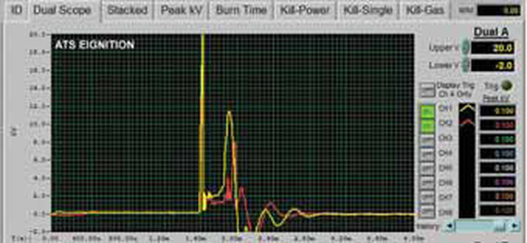
the injector is unplugged, allowing no fuel delivery to the cylinder. Note the point that the ionization changed to plasma did not differ between the yellow and red traces, indicating normal resistance in the circuit. However, the plasma waveform has more resistance due to the ack of hydrocarbons in the plasma gas. This creates the very steep voltage rise in the burn time that exceeds 10kV.
http://www.motor.com/magazine/pdfs/052005_04.pdf
http://www.motor.com/magazine/pdfs/052005_04.pdf
